


ITO and FTO are two widely used transparent conductive oxides (TCOs). Both combine high visible-light transparency with electrical conductivity, but they have different strengths. ITO generally offers lower electrical resistivity and smoother surfaces, while FTO provides excellent thermal and chemical stability and is widely used for photovoltaic, electrochemical and large-area glass applications.
The choice between ITO and FTO depends on more than conductivity and transparency. Substrate temperature, surface morphology, chemical environment, deposition method, material availability and application requirements should also be considered.
1. ITO vs FTO at a Glance
| Property | ITO | FTO |
|---|---|---|
| Full name | Indium Tin Oxide | Fluorine-Doped Tin Oxide |
| Main composition | In₂O₃ doped with Sn | SnO₂ doped with F |
| Crystal structure | Cubic bixbyite-type | Tetragonal rutile-type |
| Electrical conductivity | Generally higher | Generally lower |
| Visible-light transparency | High | High |
| Surface morphology | Generally smoother | Often more textured |
| Thermal stability | Good | Excellent |
| Chemical stability | Good | Excellent |
| Indium dependence | Yes | No |
| Common deposition methods | Magnetron sputtering, evaporation | CVD, spray pyrolysis, sputtering |
| Typical applications | Displays, touchscreens, OLEDs, optoelectronics | Solar cells, electrochemical devices, transparent heaters, large-area glass |
In simple terms, ITO is generally selected when low resistivity and smooth transparent electrodes are important, while FTO is often selected when thermal stability, chemical resistance and large-area processing are priorities.
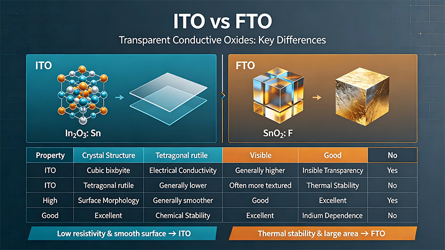
2. ITO vs FTO: Material Structure and Doping Mechanism
ITO: Tin-Doped Indium Oxide
ITO, or indium tin oxide, is based on indium oxide (In₂O₃) doped with tin. In₂O₃ typically has a bixbyite-type cubic crystal structure.
When Sn⁴⁺ substitutes for In³⁺, additional electrons can be introduced into the material, increasing its n-type conductivity. Oxygen vacancies and the film’s microstructure also influence carrier concentration and mobility.
Therefore, ITO conductivity depends on several factors, including:
- Tin concentration
- Oxygen stoichiometry
- Oxygen vacancies
- Crystallinity
- Deposition temperature
- Post-treatment
- FTO: Fluorine-Doped Tin Oxide
FTO is based on tin dioxide (SnO₂) with fluorine doping. SnO₂ has a rutile-type tetragonal crystal structure.
Fluorine can substitute for oxygen in the SnO₂ lattice and contribute additional free electrons:
F⁻ replacing O²⁻ → increased carrier concentration → improved conductivity
Oxygen vacancies and microstructure also contribute to the electrical properties of FTO.
The robust SnO₂ host gives FTO excellent thermal and chemical stability while maintaining good visible-light transparency.
3. Electrical Conductivity and Optical Transparency
Electrical Conductivity
ITO generally provides higher electrical conductivity and lower resistivity than FTO when both materials are optimized for transparent-electrode applications.
The conductivity of a TCO can be described by:
[
\sigma = nq\mu
]
where n is carrier concentration and μ is carrier mobility.
Increasing dopant concentration can increase the number of free carriers, but excessive doping may introduce defects and scattering that reduce mobility. Therefore, optimizing carrier concentration, mobility and film quality is essential.
Optimized ITO films can achieve resistivities in the order of 10⁻⁴ Ω·cm, although the actual value depends strongly on deposition conditions, film thickness and post-treatment.
Optical Transparency
Both ITO and FTO can provide high visible-light transmission, commonly above 80% and potentially higher depending on film design.
Optical performance depends on:
- Wavelength
- Film thickness
- Carrier concentration
- Surface roughness
- Crystallinity
- Substrate
- Deposition conditions
Neither material should simply be described as transparent across the entire infrared region. At higher carrier concentrations, free-carrier absorption and reflection can become important, particularly toward the near-infrared and infrared ranges.
Therefore, the appropriate material should be selected according to the specific wavelength range required by the application.
4. Thermal, Chemical and Surface Stability
One of the main advantages of FTO is its thermal and chemical stability.
FTO can withstand demanding processing and operating conditions and is therefore widely used in:
- Photovoltaic devices
- Electrochemical systems
- Photoelectrochemical devices
- Transparent heaters
- Smart windows
- Defogging and de-icing glass
ITO also has good chemical stability under normal operating conditions, but its performance can be more sensitive to processing atmosphere, temperature and chemical environment.
Surface morphology is another important difference. Optimized ITO films can provide relatively smooth surfaces, which is beneficial for multilayer electronic devices. Commercial FTO films are often more textured. This texture can increase light scattering and may be beneficial in photovoltaic and photoelectrochemical applications, but excessive roughness can complicate ultrathin multilayer structures.
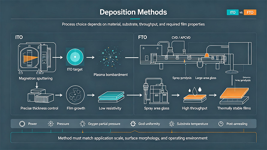
5. Deposition Methods
ITO Deposition
Magnetron sputtering is one of the most important methods for producing high-performance ITO films.
An ITO target is placed in a vacuum chamber and bombarded by plasma ions. The sputtered material deposits on the substrate to form a conductive transparent film.
Key advantages include:
- Precise thickness control
- Good film uniformity
- Low resistivity
- Large-area deposition
- Good control of optical and electrical properties
During ITO sputtering, target density, composition, plasma stability and cooling conditions can affect film quality. See our guide to ITO sputtering target problems and solutions for more details.
FTO Deposition
FTO can be produced using:
- Chemical Vapor Deposition (CVD)
- Atmospheric Pressure CVD (APCVD)
- Spray pyrolysis
- Magnetron sputtering
- Sol-gel methods
CVD and spray pyrolysis are particularly important for large-area FTO-coated glass. These processes are suitable for scalable production and can produce conductive films with good transparency and thermal stability.
The deposition method should therefore be considered together with the required substrate, film thickness, surface morphology and production scale.
6. ITO vs FTO Applications
| Application | ITO | FTO | Typical Reason |
|---|---|---|---|
| Displays | Widely used | Less common | Low resistivity and smooth transparent electrodes |
| Touchscreens | Widely used | Less common | High transparency and electrical conductivity |
| OLEDs | Widely used | Less common | Transparent electrode performance and smooth surface |
| Solar cells | Widely used | Widely used | Transparent conductive electrode requirements |
| Dye-sensitized solar cells (DSSC) | Used | Widely used | Thermal stability and textured surface |
| Photoelectrochemical (PEC) devices | Used | Widely used | Chemical and thermal stability |
| Transparent heaters | Used | Widely used | Thermal stability and large-area conductive glass |
| Smart windows | Used | Widely used | Large-area processing and environmental stability |
ITO for Displays and Touchscreens
ITO is widely used for displays, touchscreens, OLEDs and other transparent electronic devices because it combines low resistivity, high visible transparency and mature sputtering technology.
FTO for Photovoltaic and Electrochemical Applications
FTO is particularly common in dye-sensitized solar cells, photovoltaic research, photoelectrochemical systems and electrochemical devices. Its thermal and chemical stability makes it suitable for processes and environments where ITO may be less suitable.
FTO is also attractive for transparent heating, defogging and de-icing applications because it can maintain conductive performance under elevated temperatures.
7. Material Supply and Resource Considerations
A significant difference between ITO and FTO is their raw-material composition.
ITO contains indium, while FTO is based on tin oxide and does not require indium. This makes material efficiency, recycling and supply-chain considerations increasingly relevant when selecting a transparent conductive material for large-scale applications.
For European manufacturing, factors such as:
- Material availability
- Resource efficiency
- Recycling
- Supply-chain resilience
- Long-term cost stability
may therefore be considered alongside technical performance.
The EU Critical Raw Materials framework also places emphasis on secure and sustainable access to raw materials, resource efficiency and circularity.
This does not mean that FTO universally replaces ITO. Instead, the absence of indium can be an important consideration when evaluating FTO for suitable applications.
8. ITO vs FTO: How to Choose?
Consider ITO when:
- Very low electrical resistivity is required
- A relatively smooth transparent electrode is important
- The application involves displays or touchscreens
- High-performance optoelectronic electrodes are required
- Magnetron sputtering is part of the manufacturing process
Consider FTO when:
- High-temperature processing or operation is required
- Chemical and environmental stability is important
- Large-area conductive glass is required
- The application involves photovoltaics or electrochemical devices
- Reducing dependence on indium is desirable
- A textured conductive surface is acceptable or beneficial
ITO and FTO should therefore be selected according to the complete device architecture, deposition process and operating environment rather than conductivity or transparency alone.
9. Frequently Asked Questions
1. Is ITO more conductive than FTO?
Yes. Optimized ITO films generally provide lower electrical resistivity and higher conductivity than FTO films.
2. Which is more thermally stable, ITO or FTO?
FTO generally provides better thermal stability and is widely used in applications involving elevated processing or operating temperatures.
3. Is FTO cheaper than ITO?
FTO can provide a material and supply-chain advantage because it does not require indium. However, actual cost depends on substrate, film thickness, deposition method and production scale.
4. Which is better for solar cells, ITO or FTO?
Both are used in solar-cell technologies. FTO is particularly common in dye-sensitized and photoelectrochemical systems, while ITO is also widely used where low resistivity and specific optical or surface properties are required.
5. Why is ITO widely used for touchscreens?
ITO combines high visible transparency, low electrical resistivity and mature thin-film deposition technology, making it suitable for transparent electronic electrodes.
6. Can FTO replace ITO?
FTO can replace ITO in some applications, particularly where thermal stability, chemical resistance or large-area processing is important. However, it is not a universal substitute because the two materials have different electrical, optical, surface and processing characteristics.
Key Takeaway
ITO and FTO are complementary transparent conductive oxides rather than direct one-to-one substitutes.
ITO generally offers lower resistivity, high visible transparency and smoother surfaces, making it widely used in displays, touchscreens and high-performance transparent electrodes.
FTO provides excellent thermal and chemical stability, does not require indium and is widely used in photovoltaic, electrochemical, transparent heating and large-area glass applications.
The optimal choice depends on the required electrical performance, optical range, surface morphology, temperature, chemical environment, deposition process and material-supply considerations.
References
- [1] Granqvist, C. G.; Hultåker, A. Transparent and conducting ITO films: new developments and applications. Thin Solid Films, 2002, 411, 1–5.
- [2] Minami, T. Present status of transparent conducting oxide thin-film development for Indium-Tin-Oxide (ITO) substitutes. Thin Solid Films, 2008, 516, 5822–5828.
- [3] Tin oxide for optoelectronic, photovoltaic and energy storage devices: a review. Journal of Materials Chemistry A, 2021.
- [4] Noor, N.; Parkin, I. P. Enhanced transparent-conducting fluorine-doped tin oxide films formed by Aerosol-Assisted Chemical Vapour Deposition. Journal of Materials Chemistry, 2013.
- [5] European Union. Regulation (EU) 2024/1252 establishing a framework for ensuring a secure and sustainable supply of critical raw materials.
Further Reading
- Indium Tin Oxide Targets (ITO) – Overview of ITO target composition, properties, preparation, and applications.
- ITO Sputtering Target Problems and Solutions – Common ITO target problems and practical solutions.
- Why Do ITO Sputtering Targets Crack or Explode? Sintering Structure and Stress Control Explained
- ITO Target Nodule Formation During Sputtering – Mechanisms and prevention of nodule formation during sputtering.
Need a Custom Transparent Conductive Material?
VIMATERIAL supplies ITO and other advanced materials for thin-film, semiconductor, photovoltaic and optoelectronic applications, with options for different purities, dimensions and target configurations.
Need a Custom Material Solution? Contact VIMATERIAL to discuss your required material specification, target dimensions, purity and application requirements.